THE PACKAGE LIBRARY
Overview
A package is a collection of pads and silk screen graphics used to site a component on the board. A library of many common package styles is provided and this will save you a great deal of time compared with manual methods of PCB layout. The supplied libraries include over two thousand IPC-7351 named land patterns covering the common surface mount families and BGA packages, all at the standard's Nominal density level, so using a library part means the footprint geometry and naming comply with the IPC-7351 land pattern standard. However there will be occasions when you will have to create your own packages, and the steps to follow are set out below.
While the following topics are a detailed explanation of how to create component parts in Proteus, in practise this should almost never be necessary. In addition to the many installed libraries the schematic library picker includes a web search which enables you to import from over 15 million library parts. When you import, both the schematic component and the PCB footprint will be brought in (in most cases, also the 3D STEP file). There is also a FOC part creation service so manual footprint creation should not be something you need to do.
For those customers without a valid USC (who can't therefore use the web search in the schematic library picker), you can still use the universal part importer provides support for almost all third party part vendors (Ultra-Librarian, Samacsys, SnapEDA, etc.). If the part doesn't exist in Proteus itself the next step is to search for and then import it directly from a third party vendor. This is discussed in some detail in the importer help file and shown on our Youtube Channel.
Making a Package
To make a new library package:
-
Select the appropriate pad shape icons and place the pads of the package as required. Use the Layer Selector to place the pads on the appropriate layers. See below for more information.
- By default, Proteus will give the pins numbers from '1' upwards, numbering them in the order they were placed. If this is not what is required, you must either renumber them with the Automatic Name Generator, or else edit them manually. See below for more information.
- Select the appropriate 2D graphics icons and place silk screen graphics as required. A package can have legends on both the component side and solder side screens; these will be swapped if the package is placed with the mirror icon active.
- Tag all the objects by dragging a box round them.
- Invoke the Make Package command on the Library menu. The Make Package dialogue form will appear as shown below. It has three tabs: Indexing and Library Selection, 3D Mechanical Model and 3D Visual Model.

- On the Indexing and Library Selection tab, enter a name, category, type, sub-category and description for the new package and then choose a package library to store it in, typically USERPKG.LIB. Each of the category, type and sub-category fields has a New button beside it so that you can add a classification that does not exist yet. If you would rather type the indexing information directly rather than pick it from the lists, tick Advanced Mode (Edit Manually). When you are done you can either move on to one of the 3D tabs or simply commit the part to the library with no 3D information.

- If you have a STEP model for the part, attach it on the 3D Mechanical Model tab. This is the model that drives mechanical clearance checking and the export of the board to MCAD.
- If you would rather build the appearance of the part from Proteus primitives, use the 3D Visual Model tab instead and enter the 3D information according to the provided syntax. The job is greatly aided by a 3D Preview on the dialogue form which will update live as parameters are entered and adjusted. Whichever route you take, the model is stored with the package and will appear in the 3D Viewer henceforth.
-
Click OK to commit the package, together with any 3D information you have supplied, into the specified library.
A package must have at least one pin. If nothing you tagged is a pad, Proteus reports that it cannot make a package with no pins and abandons the command. This is the commonest first-time failure and it usually means the pads were left outside the tag box. You will also be turned away before the dialogue appears if every package library is read only or full, in which case create a writable library in Library Manager first.
Note that the description you enter via the Make Package dialogue form will be used via the Library Browser when searching via keywords. While not of particular importance in our test case you should give some thought when creating a part to ensure that the description contains keywords that you would use to identify the part during a search
The reference or 'anchor point' for a package can be determined by placing the ORIGIN marker. If there is no ORIGIN marker, the reference will be the centre of the first pin placed. Markers are placed in 2D Graphics Markers Mode.
It is also possible to define non-default positions for the reference and/or value labels. To do this, place the REFERENCE or VALUE markers at the required position(s).
See Also:
APPENDIX: Creating New Packages (Tutorial)
Creating Advanced Footprints: QFN with Thermal Pad (Stipled Paste Mask).
Creating Advanced Footprints: Button Pads and Touch Pads
Storing Vias and Breakout/Fanout tracks in the Libraries
Storing Vias and Breakout Tracks with a Package
A package is not restricted to pads and silk screen graphics. If you tag vias and copper tracks along with the pads before invoking Make Package, they are stored in the library part as well, and they come back every time the part is placed. This is how a BGA escape pattern or a fanout that took an afternoon to get right is made reusable: work it out once on a scrap layout, tag the whole thing, and store it as the footprint.
What is collected:
- Tagged vias become extra pins of the package, carrying no pin number. They do not count towards the pin total that the netlist has to match, so adding them does not affect netlisting.
- Tagged tracks on the top and bottom copper layers are stored as copper and reappear with the part.
- Tagged tracks on the top and bottom silk screen layers are converted into 2D graphics polylines, so they become part of the legend rather than part of the copper.
Choosing the Correct Layers for the Pins
Ordinary pad styles can be placed on single copper layers, or on all the copper layers as defined by the current setting of the Layer Selector.
- For ordinary through hole parts, you should place the pads on all the layers.
- For SMT parts, you should place the pads on the top layer only. If such a part is placed on the Solder Side, the pads will be automatically transferred to the bottom copper layer.
- For doubled sided edge connectors, you should place separate fingers on both the top and bottom copper layers.
- If you need different shaped pads on different layers for a through hole pin, you should use pad stacks as defined under Pad Stacks.
The Replicate Command
Proteus layout provides a command to replicate tagged objects at a specified spacing. This will operate in X and/or Y when you are in cartesian co-ordinates and on an angular step about an origin when you are in polar co-ordinates (View menu toggle). This can be extremely useful when creating new packages as you can use it to lay out rows of pads with the spacings entered directly from the keyboard.
Replicate is invoked from the Edit menu, or from the right-click menu of a selection. There are two dialogue forms behind it, and which one you get depends on the polar co-ordinate toggle:
- Replicate, the cartesian form, which offers X-Step, Y-Step and No. of Copies, a choice of whether the step is an offset or a separation, and a Re-Annotation group with Bind To and Increment for replicating blocks of annotated circuitry.
- Radial Replicate, the polar form, which offers No. of Copies, Angular Step, a radial offset or separation, and a Radial Origin selector letting you pivot about the current origin, the output origin or the database origin.
To place a row of pads by replication (Cartesian)
- Make sure that the Polar Co-ordinate toggle is off (View Menu).
- Place a single pad of the require style at the first position of the row.
- Ensure no other objects are tagged, and then tag the pad by right clicking on it.
- Invoke the Replicate command from the Edit menu, or from the right-click menu of the selection.
- Enter the required X-Step (for a row) or Y-Step (for a column). Remember to enter a dimension suffix for these values, for example 20th or 1.5mm.
- Enter the number of copies. This should be one less than the total number of pads required, as you have placed one already.
- Click OK, and Proteus will replicate the original pad as specified.
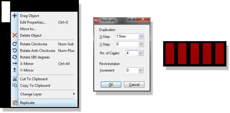
The Replicate dialogue and the row of pads it produces from a single placed pad
To place a circle of pads by replication (Polar)
- Turn the Polar Co-ordinate toggle on (View menu).
- Decide what the pads are to be arranged around. If you want them centred on a point of your own choosing, place a false origin there with the O shortcut key; otherwise you can pivot about the output origin or the database origin, chosen on the dialogue form itself.
- Orient your first pad if necessary and then place it at the radius distance from that centre.
- Tag the pad and invoke Replicate. The Radial Replicate form appears.
- Set Radial Origin to the point you are pivoting about, then specify the Angular Step (e.g. 20) and the number of copies (e.g. 17).
- Click OK, and Proteus will replicate the original pad as specified.
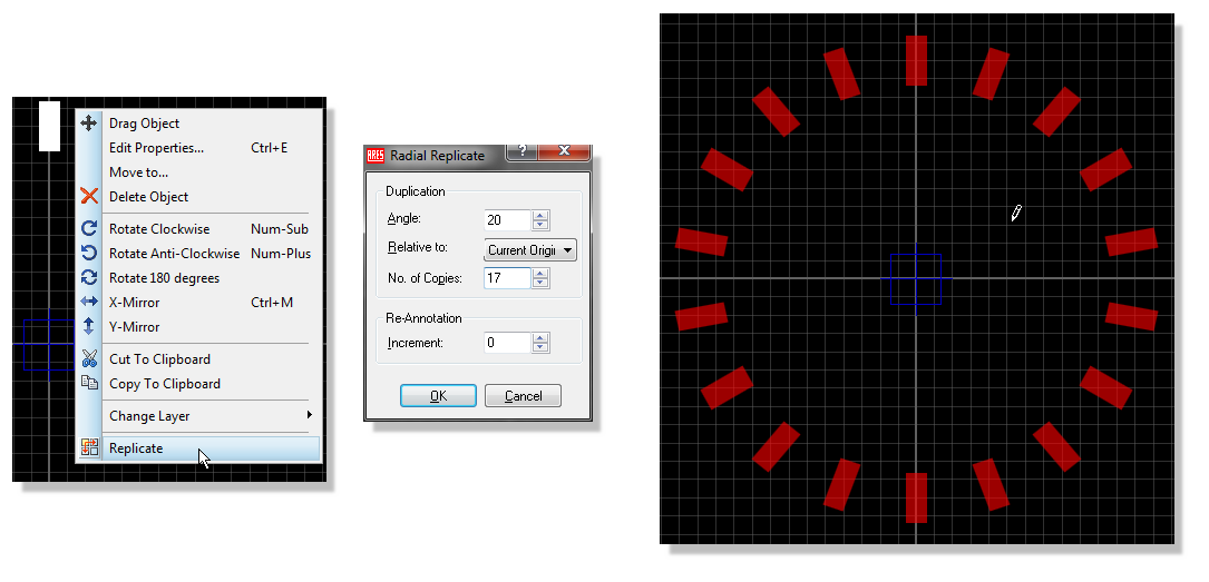
The Radial Replicate dialogue and the circle of pads it produces from a single placed pad
This technique is demonstrated in the appendix to the tutorial in the documentation.
You can extend this principle to creating grids of pads by replicating a pre-laid row.
You can also use the Replicate command to duplicate identical blocks of circuitry. The procedure for this is :
1) Design one block inside a sub-circuit on the schematic.
2) Drag a box around the sub-circuit and block copy to make the second copy. Change the name of the block but not the name of the circuit.
3) Place and route one of the blocks.
4) Drag a selection box around the circuitry on the layout and select the Replicate command.
5) Choose the name of the second block from the bind to combo box
Pin Numbering
When a netlist is loaded, Proteus attempts to match pin numbers appearing in the netlist with the pin numbers assigned to the pins of the component packages. Where a match cannot be found, this is an error and either the schematic library part or the layout library part must be changed.
When you are defining a layout library part, there are three ways to control the pin numbering:
- By default, the pins will be numbering from '1' upwards in the order that they were placed.
- If you invoke the Automatic Name Generator command on the Tools menu, you can then click on the pads in any order you like to assign incrementing pin numbers.
- You can key the numbers in one at a time. Enter Selection Mode, then either double click the pad, or right click it and choose Edit Properties, to open its edit dialogue and type the pin number.
Note that trying to use a mix of default and manual pin numbering is likely to lead you to confusion and mistakes.
Other Points
Proteus normally chooses locations for the part ID and value; these labels can always be moved after a part has been placed by tagging it, pointing at the label you wish to move, and dragging with the left mouse button depressed. The locations chosen will generally be good enough as is, unless many components are closely packed together.
However, if you wish to force the label to a particular default position, you can use the REFERENCE and VALUE markers, as described above.
The size of the labels is set by the Set Text Style command on the Technology menu. This will apply globally except for labels whose size has been manually edited.
Editing a Package
To edit and existing library package
- Enter Package Mode.
- Pick the package to be edited from the library (using the toggle on the Object Selector) and place it on the work area.
- Tag the package with the right hand mouse button and then invoke the Decompose command from the context menu. This will break the package into its constituent pads and 2D graphics and also place an ORIGIN marker at the location of the part's placement reference.
- Edit the pads and graphics as required.
- When you have finished you can use the Make Package command to re-store the package either with the same name as before, or as a new part.
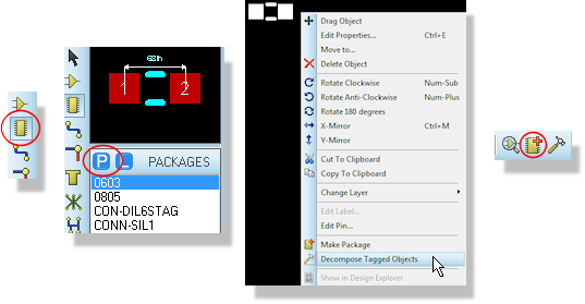
Pick and place the package > Decompose and amend > re-make the package
Of course, if the original package came from PACKAGE, which is normally read only, you will have to store it back to USERPKG. We recommend against using Library Manager to re-copy the part to PACKAGE as this can cause problems for you when we issue a new PACKAGE.LIB - how are you going to sort out which parts have been edited by you in order to preserve them?
Note that the pins will carry the pin numbers from the original package so decomposing a DIL14, sticking two pins on the end, and then re-making is not the way to make a DIL16 unless you are prepared the to re-number all the pins manually.